(Click for full-size picture)
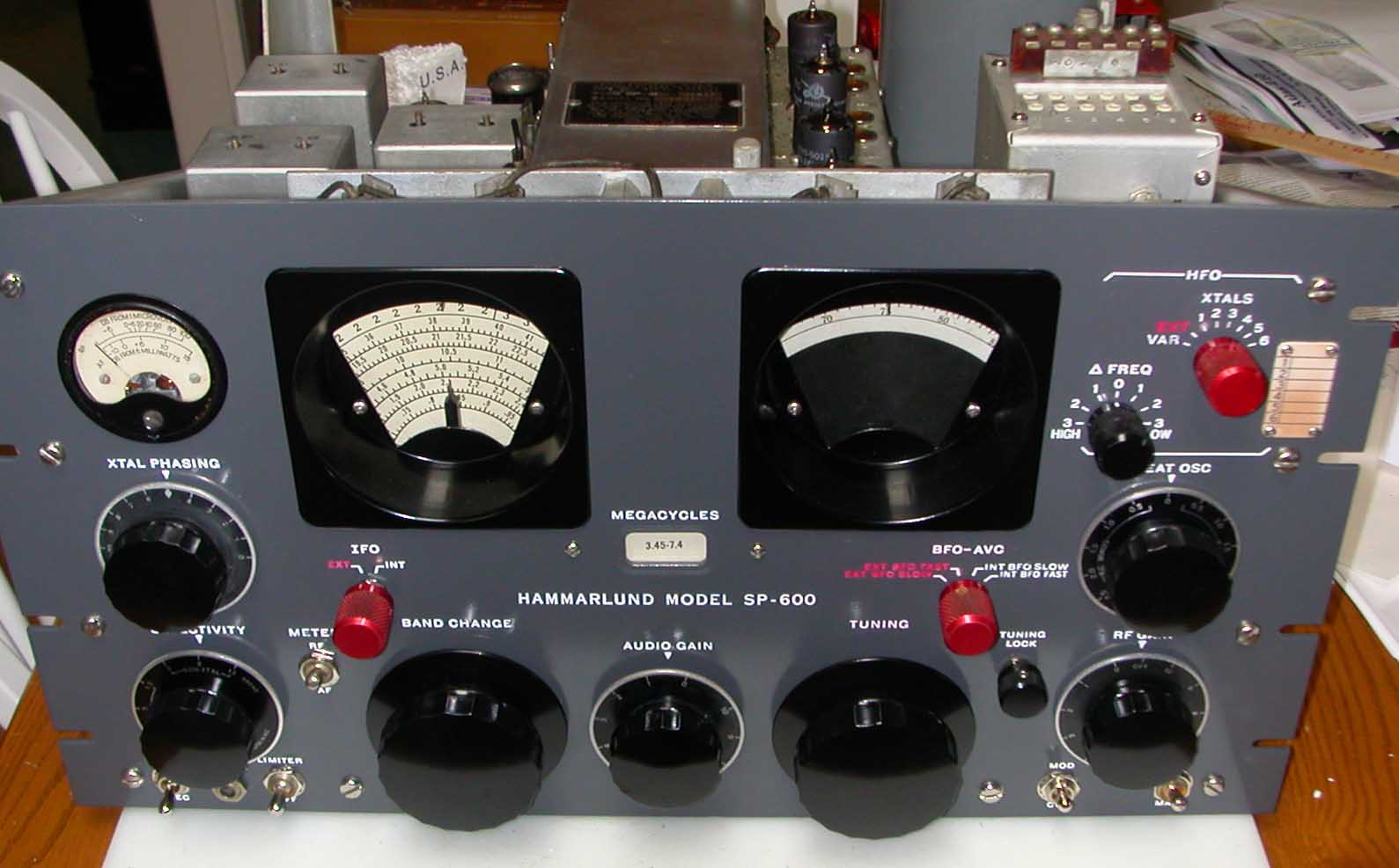
I did refinish the front panel. I used a darker grey so the engraving and the dials stand out better. I did repaint the black knobs on this one (not the red ones). They were quite dull. I did not try to repaint the meter. I was worried that some paint would get into the mechanism. The frequency and vernier dials were quite clear on this unit, so I did not replace them with dial overlays. I did clean them up a bit. Note that in the process of restoration, I completely disassemble the receiver - I take all the gears off on the front panel and remove all the major assemblies (that come off, that is).
I will warn you that the unit, in person, doesn't look as good as these pictures look. I don't quite know why, but the pictures look great, whereas the actual unit has some nicks and scrapes and rust spots on the chassis. I replaced a lot (not all) of the hardware with stanless - especially on the front panel. Every time I took a screw out, I replaced it with stainless, and every time there was a markedly rusty nut or screw that I could get to, I replaced it.
(Click for full-size picture)
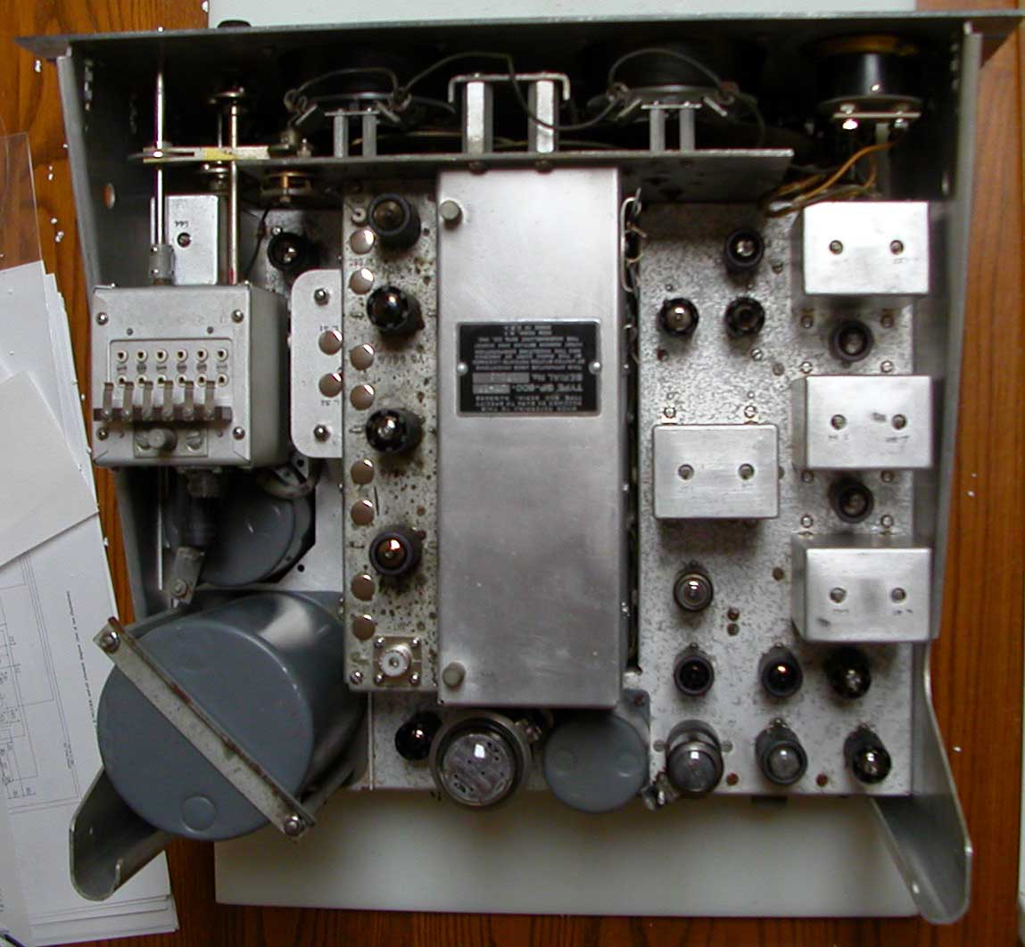
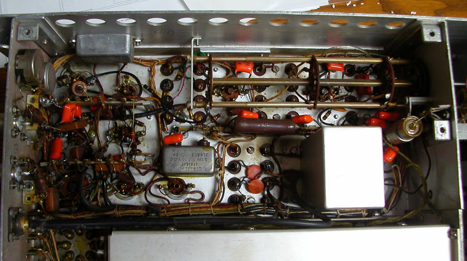
De-Oxit was applied to all the tube sockets. The chassis did not need any work - it was relatively clean and square. It was apparent that this receiver had not been dropped or otherwise mishandled. There were no bent edges or crushed corners. I replaced the missing tube hold-down clips on V3, and V17.
(Click for full-size picture)
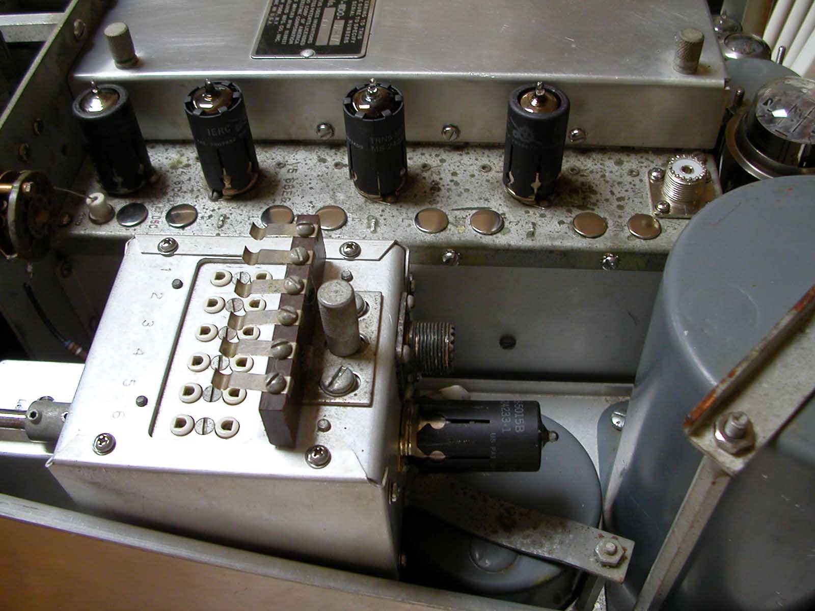
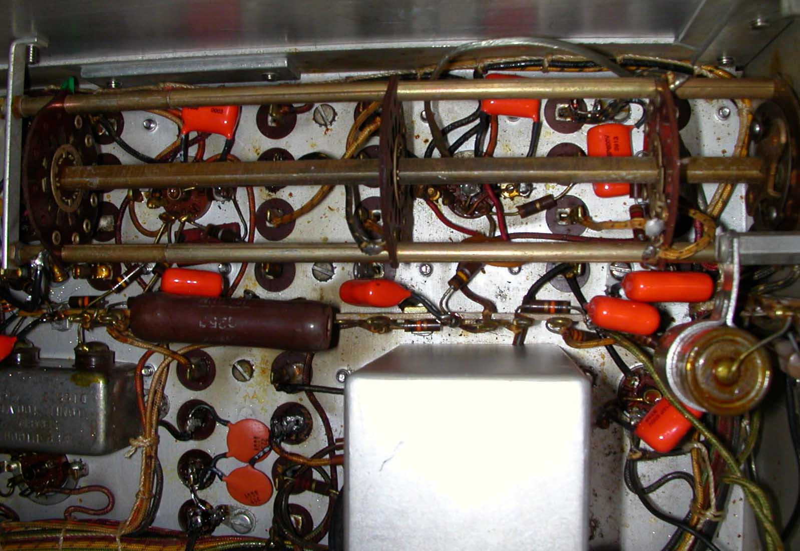
You notice that the FCU (the crystal oscillator) has the 6AH6 tube on this model (as opposed to the 6AC7 on other models).
(Click for full-size picture)
(Click for full-size picture)
(Click for full-size picture)