(Click for full-size picture)

|
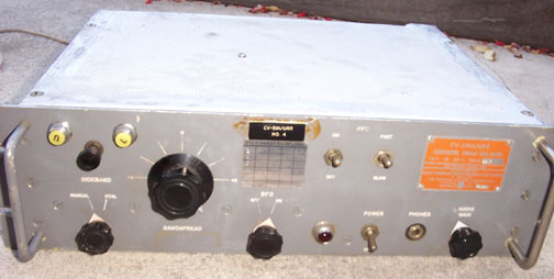
This is a Technical Materials, Inc CV-591A/URR, serial number 2207 SSB adaptor. It takes
the IF output from any number of receivers, such as the Collins R-390 or R-390A, or the
Hammarlund SP-600. It has had up to field change
5 performed so it has the extra 14 kHz filter in the audio output path. This is also known
as the TMC MSR-4.
This unit was in quite good shape - a tribute to how well-made these devices were. This one
is a bit unusual in that it has both the top and bottom covers. I did not do much on the cosmetics
except to clean it up carefully. I did go through the electrics of the entire unit in some
detail, replacing any parts that were leaky or out-of-spec. I also replaced all the tube
shields with the black IERC type. (the two missing tubes are deliberate - it is part of
field change 5 that they disabled the remote control interface. Probably just as well).
I can say that this is one of the best-sounding units I have ever heard.
If you have not heard the performance of these units, it is quite remarkable how clean
the SSB is. It sounds a lot like AM. The CV-591 has several additional filters to knock
out nearby interference. These are all LC filters - no crystal filtering in this unit.
|
(Click for full-size picture)
|
This shows the underside of the power supply. I removed the old (leaky) electrolytic capacitors
and replaced them with under-the-chassis modern high-ripple long-life alluminum electrolytics of
considerably higher capacitance. I can detect no 60 Hz ripple anywhere. Some previous owner
had removed the power entry connector and put a household electric cable clamp on it. I did not
try to change that. I did replace the fuse holder, however, which was falling apart. Note that
the choke below my new capacitors has dribbled a bit of brown stuff down the chassis. This
is L1, the 15 Henry first power filter choke. I believe what happened is that some time in
the past, the filter capacitor decided to short out. This probably heated up the choke so
much that it bled over the chasis. I have tested the choke carefully, and concluded that it
is in perfect operating condition. Again, some kind of testiment to how rugged these units really are.
|
(Click for full-size picture)
|
This is just to show you how well-built these units are. Every part is securely held down
on these component carrier strips. Note the L-brackets that hold the component carriers - those
parts aren't going anywhere! Very few of the capacitors showed any significant leakage, so I
did not have a lot to do here. The relays and the relay contacts were in perfect working order.
|
(Click for full-size picture)

|
This is a closeup of L3, a 3/4 Henry inductor. This was added as part of FC 5. It reduces the
amount of the 17 kHz IF frequency. This may be part of the reason for the great sound of this unit.
|
(Click for full-size picture)
|
I tested all the tubes and replaced any weak or dead ones. This unit, as part of one of the
field changes, already has a silicon replacement for the rectifier. I did not fiddle with it
as it seemed to be working quite well.
|